Kirk Martinez
History of Art Department
Birkbeck College & University College of London
London WCIH OPD, England
Abstract: VASARI: Visual Art System for Archiving and Retrieval of Images, is a project funded by the European Community ESPRIT II scheme. It aims to show that high resolution colormetric imaging directly from paintings is feasible. One aim is to replace photography as a recording system, so the images have to compete with transparencies. Such a system can be used to create more accurate permanent records for research, conservation, teaching, printing, etc. The images are taken at a resolution of 10 to 20 pels per millimeter of painting so the imaging system has to have scalable resolution. This is achieved by moving the camera and mosaicing as many frames of a high resolution camera as necessary. Seven bands of the spec-trum are used to provide accurate color measurement. This presentation will give an overview of the whole project: hardware, software and theory. It thus repre-sents the work of the VASARI Consortium: Birkbeck College (UK), The National Gallery (UK), Brameur Ltd (UK), Telecom Paris, Thomson-CSF LER (France), The Dorner Institute (Munich), TUV (Munich), LRMF (Paris), SIDAC (Italy).
VASARI: Visual Art System for Archiving and Retrieval of Images, is a project funded by the European Community ESPRIT II scheme. It aims to show that high resolution color-metric imaging directly from paintings is feasible. This makes it possible to replace photo-graphy as a recording method. The digital images can be more accurate in terms of color and do not age like photographic materials. Such a system can be used to create more accurate permanent records for research, conservation, teaching, printing etc. VASARI is a 36 month project which started in July 1989 with funding of around US$2 million and involves gallery scientific departments, universities and companies from around Europe.
2. THE VASARI SYSTEM
2.1. Resolution
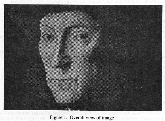
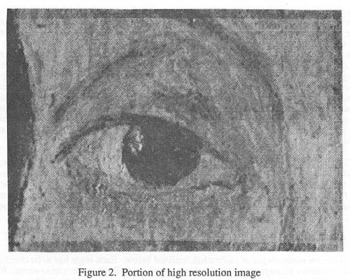
Sufficient resolution is required to be able to see cracks and brushstrokes, so the number of pels (picture elements) in an image must relate to the picture size and was determined to be 10-20 per mm of original (Martinez & Hamber, 1989). This is based on a study of crack sizes which showed major cracks to be typically around 0.1mm wide (which requires 20 pels/mm). Coincidentally 12 pels/mm (300 per inch) is a common document scanning resolution. A 35mm transparency is equivalent to around 3000 lines, which is a too low for large works. A 35mm transparency of a 30cm high work would give an equivalent resolution of 10 pels/mm. So clearly if larger images are photographed less detail is captured than with the VASARI system. However 10x8" transparencies have a very high resolution: giving around 10 pels/mm for a 2.4m high work. Figure 1 shows an overview of a 3000x2000 pel image and Figure 2 shows a 400x300 pel area of the high resolution image.
Each square metre of painting requires at least 10000x10000 pels but no commercial digital camera has a high enough resolution to create such images in one exposure. This led to a decision to take as many frames as necessary to cover painting and then join them together. This meant using a computer controlled camera positioning system. This mosaicing technique can produce the high resolution required by using a commercially available camera and without reliance on a particular technology.
2.2. The Camera
The Progres 3000 camera (Lenz, 1990), designed at the technical university of Munich and marketed by Kontron was chosen because it produces 3000x2300 pel images. This reduces the amount of mosaicing necessary. It does this by using a 500x290 CCD which has smaller than normal sensor sites which do not cover the whole area of the chip. The chip is moved minute amounts by piezo-electric ceramic actuators so that multiple exposures can be
interleaved to cover the whole image area. By taking 48 images (a 6x8 motion) the full resolution is obtained but a lower resolution image can be taken to allow easy focusing for example.
2.3. The Positioning System
A computer-driven positioning system is used to move the camera accurately over the plane of the painting. By knowing the resolution, the camera can be moved so that successive exposures just overlap. The camera can also be moved forwards and backwards for fine automatic focusing. The lighting system is mounted with the camera so that the same light distribution occurs for each exposure and can be compensated for. The main axes cover 1m (1.5m in Munich) in steps of 0.05mm. The first scanner was built in the National Gallery, London (by Time & Precision, UK) and a second design was built in the Dörner Institute in Munich (by ALCO, Germany).
2.4. Mosaicing
To allow for positioning errors, the small overlap between frames is analyzed to guide the frame-joining accurately. This involves correlating areas to find similarities or tie points, then joining the frames using the measurements. One problem with mosaicing is that if too many frames are joined, any errors accumulate, so there is a practical limit to the number of sub-frames which can be joined. To accurately correct for geometric errors due to lenses etc re-quires extensive processing, so they have to be avoided or minimized: a good lens is essential.
2.5. Colour Measurement
Each point of the image is measured in terms of a standard color space (CIE XYZ) to allow accurate comparison and reproduction (Saunders & Hamber, 1990; Saunders, 1989). In theory three filters matched to the eye's red, green and blue sensitivities could be used to take three exposures which calibrate easily. Unfortunately obtaining these is nearly impossible, so we are investigating the use of seven filters (50nm bandpass) spanning the visible spectrum. These seven channels can be combined to give accurate measurements. A model of the camera response is used which groups together unknown elements such as the light, lens and sensor into a matrix of coefficients. These can be calculated by imaging seven known colors and solving the equations. The model can then be used to convert the image of the painting into XYZ color values. In practice there are many stages where errors occur and we are constantly refining the technique. For example the choice of the seven known colors can affect the overall accuracy. By imaging many accurate samples (a Macbeth chart) any errors can be expressed in terms of "just noticeable differences" to show the accuracy. A uniform color space(Luo & Rigg, 1986) based on CIE Lab 1976 and the CMC equations gives a difference of 1 for such an error.
To avoid taking images through the thick interference filters the light passes through them instead, illuminating the painting with seven colors. A fibre-optic system allows the use of a single light source which can also illuminate from several points from split fibre bundles. One set of filters is used in a computer-controlled wheel inside the light box. The light system is mounted with the camera and moves with it. This makes lighting distribution correction easier, as it is the same for each sub-frame.
2.6. Calibration and acquisition
There are many stages of calibration, outlined below.
Each stage has to be checked carefully as errors propagate into the final
image and are difficult to trace afterwards. By specifying the target positions
such as the macbeth color chart, most of the calibration can be automated,
and the camera is being moved to each in turn. Similarly once the resolution,
location and size of the painting are known the acquisition proceeds automatically.
| Calibration | Acquisition |
| Focus camera | Check Focus |
| check lighting coverage | Measure Resolution |
| find gains for 7 channels | Acquire 7 band image blockscorrect non-linearity |
| grab white for illumination acquire grey-scale | linearity |
| generate 7 non-linearity corrections | correct illumination |
| correct illumination & non-linearity | convert to XYZ with matrix |
| measure camera values for 7 color patches | mosaic image blocks |
| generate conversion matrix | convert to RGB for a display |
The computer can move the camera backwards and forwards to automatically focus the image by measuring a "sharpness" factor based on a sum of local pel differences. This means the lens focus can be left fixed. Because the lighting is not uniform and the lens introduces vignetting, each frame must be corrected using an image of a white card. There is a large difference in response to the extreme red and blue filters and the middle green filters so the camera's computer controlled gain is set higher for the darker filters. The camera may have a non-linear response to light, especially at low levels, so it is calibrated using a grey-scale chart. Finally the image of the Macbeth chart is used, after all the appropriate corrections, to generate the conversion matrix.
2.7. Computer System
A UNIX workstation is being used (SUN Sparcstation) as it combines power with stan-dardization. 1GB of disk space and 16MB of RAM are used as well as a full color graphics system (24 bit: 16M colors). However a PC is currently used to control the camera and a microcontroller handles the scanner, lights and filter changing. The X-Windows system is used for displaying images and windows with up to 24 bits per pel. An image processing package (VIPS) has been written in C to make best use of the hardware and UNIX. All images are stored in a simple VASARI format file, which can be converted to TIFF etc.
2.8. Display
The only output technique we have worked on is the computer screen. Only 1150x900 pixels are shown on screen so pan/zoom controls allow viewing of the whole high resolution image. Displays have varying characteristics and have some limitations in the colors they can display. By using a Barco Calibrator monitor a more accurate display is possible. This monitor has its own microprocessor and can measure its own screen for calibration. The main computer can communicate with the monitor to find out its parameters and modify the image sent to it (using monitor modelling equations) so that it appears accurately.
2.9. Storage
Scanning paintings at around 10 pels/mm, involves storing 300MB per square metre for an RGB image. In practice the original seven band image must be saved for reference, but this does not have to be on-line. To avoid errors, only a lossless compression technique could be used, which would give a compression of less than 3:1. For on-line viewing of many images, compression such as JPEG can be used up to around 16:1 with invisible errors. Optical disks are the only feasible large storage medium which allow random access. Disks are available with over 3 GBytes per side and jukeboxes can hold tens of disks. We currently use a Maxoptix Tahiti 1G magneto-optical drive. One problem with such disks is their slow read
rate (around 150 kB/s).
2.10. Computer Aided Learning
High resolution images are an ideal source for lower resolution images for distribution and teaching. A CD-ROM demonstration has been made with around 250 300x200 low resolution VGA images for display on a PC, with a simple database. Experiments have also been made with Oracle and Superbase on PC systems.
2.11. Human Interface
Thomson-CSF has created a new X-Windows based human interface for VASARI. It is icon-based to allow any operation by clicking icons with a mouse. An image can be processed by simply dropping a processing icon onto an image icon. The interface also links to a data-base to allow the management of text and images. An "experts" interface to the image processing tools has also been made at the National Gallery.
3. RESULTS
Some paintings have been automatically imaged and initial results are extremely promis-ing. The color accuracy is high and increases with new developments in lighting and calibra-tion. The best accuracy achieved so far (under poor conditions) is an average color error of 4 for the Macbeth chart. Although the capture time is very long (several hours), it compares favorably with conventional photography in terms of processing time and can be reduced by program optimization and faster computer systems. Lighting problems such as specular reflection remain to be completely solved, but the project has shown conclusively that direct imaging of paintings is possible with great accuracy.
4. THOSE INVOLVED
This paper briefly presents the work of the VASARI consortium, more details will appear in specific technical papers. Those involved include:
Birkbeck College (University of London),
The National Gallery (London),
Brameur Ltd (UK),
Telecom Paris,
Thomson-CSF (Rennes France),
TÜV (Germany),
The Dörner Institute (Germany),
LRMF (France),
SIDAC (Rome), and
ESPRIT.
REFERENCES
1. K. Martinez and A. Hamber, "Towards a colormetric digital image archive for the visual arts," in Proceedings of the Society of Photo-Optical Instrumentation Engineers, v. 1073, January 1989.
2. R. Lenz, "Calibration of a color CCD camera with 3000x2300 picture elements," in Proceeding of Close Range Photogrammetry Meets Machine Vision, Zurich Switzerland, 3-7 Sept 1990. Proceedings of the SPIE, 1395: 104-111 (1990). ISBN: 0-8194-0441-1
3. D. Saunders and A. Hamber, "From pigments to pixels: Measurement and display of the color gamut of paintings," in Proceedings of the SPIE, 1250: 90-102 (1990).
4. D. R. Saunders, "The detection and measurement of color change in paintings by digital image processing," in Proceedings of the SPIE, v. 1075 (1989).
5. M.R. Luo and B. Rigg, "Uniform color space based
on the CMC color-difference formula," Journal of the Society of Dyers
and Colourists, 102: 164 (1986).